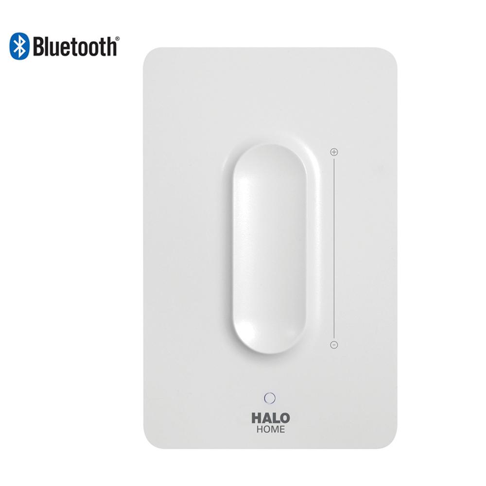
Halo Switch
HALO-LED™ Installation Instructions with Variable Speed Blowers and Communicating Thermostats
How to Switch Your Pet to Halo Simple steps for a safe and successful switch While pets get excited by the great aroma of Halo’s real WHOLE meat, poultry, and fish, their unique digestive enzymes need a little time to adapt completely to a new food. Halo True mechanical keyboard switches, which are heavier than Halo Clears, blend Topre and Cherry MX Clear force curves. Invented by Input Club and Jacob Alexander, Halo Trues use a custom spring to increase tactile feel and provide a strong bottom out-resistant force increase at the end of keystrokes. HaloWaypoint.com is the official site for the Halo universe, featuring the latest information about Halo games and media, news from 343 Industries and the home of the Halo community.
When using the HALO-LED on an HVAC unit utilizing a variable speed fan or ramping motor with communicating thermostats, the RGF Air Sensing Switch Kit (HLED-AS) or equivalent may be used. The HALO-LED is designed to power on and off with the blower of the HVAC. Unlike the REME HALO®, the HALO-LED has a longer life with the power cycling on and off as needed. In order to tie the incoming power of the HALO-LED with the HVAC blower power, an air sensing switch may be used.
NOTE: This is only a recommended installation for the air sensing switch, all wiring must be done to comply with all pertinent local codes and regulations. To avoid injury or shock hazard, ensure power is disconnected from the HVAC unit prior to any electrical work being performed.

NOTE: Air switch must be mounted in a vertical orientation as idicated in illustration below.

Halo Switches Guide

Halo Switch Wiring
- Attach the air sensing switch to the AC control panel in a suitable location within the enclosure
using the included self-tapping screws. - The air sensing switch is designed to close its internal switch when the pressure increases to a set point across the sample line connections. In order to achieve a pressure differential, use the included tubing. 2 pieces are needed. Use included grommets if holes are drilled in sheet metal. Use zip-ties as needed. Use figure below for reference.
- Connect 1 piece of tubing to the gray negative side of the air sensing switch. The other side of this tubing will need to be routed to any area on the inlet side of the blower.
- Connect another piece of tubing to the black positive side of the air sensing switch. The other side of this tubing will need to be routed to any area on the outlet side of the blower. Avoid placing tubing directly next to heating elements.
- Using the included ¼” female spade connectors, wire the system per diagram below:
- Connect 1 end of the HALO LED barrel plug wire to common on the air sensing switch.
- Connect the other end of the HALO LED barrel plug wire to 1 side of 24VAC on the supplied transformer.
- Connect the NO side of the air sensing switch to other side of 24VAC on supplied transformer.
- Power the supplied transformer by using to the appropriate connections from the HVAC system.

NOTE: REFERENCE TRANSFORMER LABELING FOR WIRING DIAGRAM

